Door handles with access control ELH -51H4
Original instructions Door handles with access control ELH - 51H4 in Polish
Sort:
Search:
INTRODUCTORY NOTES
Please read carefully before installing, connecting and using the device this user manual. In case of any problems with understanding its content please contact the seller of the device.
Self-assembly and commissioning of the device is possible provided that you use appropriate tools. However, it is recommended to assemble the device by quali-qualified staff.
Due to the possibility of damage to the access control handle:
- the device should not be installed in doors with a door closer,
- the door in which the device will be installed must be properly installed and adjusted along the door frame,
- the door leaf must close easily (not spring) and with maximum operating forces acting on the device must not exceed the thresholds specified in the device specification tion contained in this manual,
Door handles with access control should not be installed in saunas, cold rooms and other rooms, conditions in which the relative humidity and ambient temperature exceed the threshold specified specified in the technical specifications of the device.
For increased safety, it is recommended to install a recessed patent insert ELB -01,-02, -03H4 , which will also act as an additional emergency entry option.
The manufacturer is not responsible for damage that may result from incorrect installation or operation and from making independent repairs and modifications.
Remember to:
- use the device in accordance with its intended purpose, keep it away from moisture and fire,
- do not throw into fire, do not hit, crush or expose the device to damage
mechanical,
- do not clean the device with water, solvents or other chemicals,
- clean the device housing only when the power source is cut off for cleaning
you can use a damp cloth, but after using it you should wait until it is completely dry
casing drying out,
- do not make any modifications or repairs yourself
Attention!
Devices with an penetration coefficient higher than or equal to IP44 can be mounted outdoors (e.g. bell buttons, external video intercom cassettes, cameras, etc.). Information about the penetration coefficient is included in the technical specifications of the device.
1. GENERAL CHARACTERISTICS AND PURPOSE
An electronic door handle with access control easily limits access to protected rooms by unauthorized persons. It is intended for both left and right doors, and the universal mounting screw spacing of 40-45 mm allows in most cases to use a mortise lock already installed in the door.
There is a proximity key reader (Mifare 13.56 MHz) and a touch numeric keyboard on the handle body.
After bringing the key fob closer to the reader and entering the correct PIN code, the lock inside the lock is released.
2. SET CONTENTS
3. CONSTRUCTION
4. PRINCIPLE OF OPERATION
After giving an impulse from the electronic access control module, the servomotor unlocks the mechanical transmission, thus enabling the door to be opened by pressing the handle on the external part normally. The opening is signaled by a sound. The waiting period for pressing the handle is factory set to approximately 5 seconds, after which the gear is locked again and the lock switches to the waiting state for another impulse from the electronic access control module.
From the inside (of the premises), it is always possible to open the door by simply pressing the handle. After closing the open door, the latch mechanism is immediately activated, making it impossible to open the door from the outside without an impulse from the electronic access control module.
It is possible to open the lock in an emergency using a regular mechanical key, 2 of which are included in the set.
Additionally, the device has an access lock function, which allows only the administrator's code or emergency entrance key to enter the room.
INSTALLATION OF THE ELECTRONIC DOOR HANDLE
The set includes pins, sleeves and screws enabling the installation of handles in doors with a thickness of 35 ~ 65 mm. During assembly, select the appropriate length of the attached elements.
Attention!
To increase safety, electronic handles with access control are recommended to be installed in rebated doors. It is also recommended to install a lock insert in the mortise lock, thanks to which it is possible to open the lock with a key regardless of damage to the electronic handle.
Installation should be carried out with emergency keys, which may be necessary in the event of slamming a door with an unprogrammed lock. The lock should be installed on an open door leaf. After completing the installation and programming the lock, a device operation test should be performed, also on the open door leaf.
Attention!
It is recommended to install the locking handle with a pitch of 72 mm, 90 mm or 92 mm. The part of the hole intended for the lock cylinder can be covered with a suitable mounting cover, which must be purchased separately: 72 mm -> ELB-01H4, 90 mm -> ELB-02H4, 92 mm -> ELB-03H4
5.1. SETTING THE HANDLE ORIENTATION (LEFT/RIGHT DOOR)
All electronic handles are universal and can be attached to both left- and right-opening doors
5.1.1 ORIENTATION SETTING - FRONT OF THE HANDLE
To determine the opening direction of a handle with built-in access control, proceed as follows:
- unscrew the 4 screws from the base of the sign that hold the cover (Fig. 6),
- remove the cover (fig. 6, item 1-A),
- unscrew the locking screw (fig. 6, item 2-B),
- set the handle in the desired opening direction (fig. 6, position 2-C)
- tighten the locking screw,
- install the cover and tighten the mounting screws (fig. 6, item 3)
5.1.2 ORIENTATION SETTING - BACK OF THE SIGN
To set the opening direction of the handle with a built-in battery compartment, proceed as follows:
- unscrew the locking screw located next to the pin socket (fig. 7, item 1-A)
- set the handle in the desired direction (fig. 7, position 2)
- after determining the direction, screw in the screw setting the handle direction (fig. 7, position 3)
5.2. INSTALLATION OF THE PIN IN THE ELECTRONIC HANDLE
The pin should be placed in the socket located in the device body marked with a triangle, and then install the locking pin included in
PREPARING A REPLACEMENT SHAFT
If you want to use a different pin than the one included in the set, proceed as follows:
get an 8 x 8 mm pin, then measure the appropriate length and cut the pin.
Note: The pin must be cut to an appropriate length to eliminate the possibility of moving this element during use, otherwise the pin socket will be at risk of damage.
5.3 BATTERY INSTALLATION
To install the battery in the battery compartment, pry off the battery compartment cover in the upper center with a screwdriver.
Attention!
- For proper operation of the device, the use of alkaline batteries is required, do not use rechargeable batteries.
- It is recommended that the handle be installed and programmed with the door leaf open; after checking the correct operation, the door leaf can be closed.
- After inserting the batteries for the first time, the handle automatically goes into the armed state, so remember to insert the batteries after installing the electronic handle in the door leaf. If the batteries have been inserted earlier, in order to open the door, you must use the emergency key, which is recommended to have with you during the installation.
The electromechanical door handle is powered by 4 DC 1.5 V AA alkaline batteries and can operate for approximately 1 year on one set of batteries.
5.4. ASSEMBLY DIAGRAM
To install an electronic door handle, proceed as follows:
d. install the rubber washer as shown in the drawing
and screw the sleeves to the front handle bodyki,
e. run the connecting cables coming from the outer part of the escutcheon above the mortise lock,
f. transfer the outer part together with the connecting sleeves me through the door leaf with the previously installed one lock
5.5 EMERGENCY OPENING METHOD
If you need to enter the premises, use the emergency key to insert the emergency key into the insert located at the bottom of the device on the access control side and turn the key to the right until you feel resistance. Then, by pressing the handle, you can enter the room.
Attention !
It is possible to provide emergency power to the handle in the event of a discharged battery. For this purpose, use the USB C socket (DC 5 V) located at the bottom of the external handle.
6. ELECTRONIC LOCKING LOCK
"Włączona funkcja blokady" - Blocking function ACTIVATED
"Wyłączona funkcja blokady" - Blocking function DEACTIVATED
1. To enable the electronic lock function, activate the "privacy lock" function in the application;
2. When the button is in the red position, it is in the locked state and can only be unlocked by the administrator code or mechanical key.
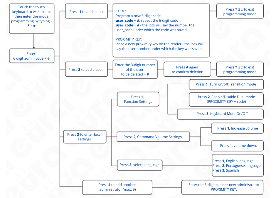
7. PROGRAMMING AND OPERATING THE ELECTRONIC HANDLE WITH ACCESS CONTROL
7.1. ADMIN CODE
When logging into the programming mode for the first time, we must enter the administrator code.
For this purpose:
- wake up the device's keyboard by touching it,
- enter * + #
- assign a 6-digit administrator code + #
- repeat the 6-digit administrator code + #,
- after correctly registering the administrator password, the device will provide the administrator number -
tora and will redirect us to the settings panel.
* - cancel, undo, exit and delete.
# - confirm, exit
7.1.1. SETTINGS
 7.2. MODES PROGRAMMING
How to set Passage Mode (lock always in "unlocked" state, no need for verification):
1. Press the sequence "0" + "#" + admin password + "#".
2. After successfully completing this operation, you will receive a confirmation message.
3. Door Mode has been activated, which means that the lock will be unlocked after using the user's proximity code or key until the user enters the user's proximity code or key again.
4. To deactivate the transition mode, repeat the sequence from step one.
7.3 SETTING THE AUTOMATIC UNLOCK TIME
To change the automatic locking time (you can choose the locking time: 5S, 10S, 15S, 20S):
1. To set Auto Lock for 5 seconds, press "1" + "#" + admin password + "#".
2. To set Auto Lock for 10 seconds, press "2" + "#" + admin password + "#".
3. To set Auto Lock for 15 seconds, press "3" + "#" + admin password + "#".
4. To set Auto Lock for 20 seconds, press "4" + "#" + admin password + "#".
After performing the appropriate operation, the lock will be automatically blocked after the selected time.
8. UNLOCKING AND LOCKING THE LOCK
• Unlocking the lock: In order to enter the protected room using the electronic door handle, activate the urad code lock, then enter the 6-digit user code and confirm it with #.
• Blocking the lock: entering an incorrect code 5 times or applying an unprogrammed proximity key will result in blocking the lock for approximately 90 seconds.
ATTENTION
When the battery level is low, the door handle will activate an alarm signal (single siren sound) and will generate the message "Low power please change battery!
9. RESET BUTTON
There is a handle reset button under the battery cover. To perform a reset, press the reset button for 6 seconds. The reset will be confirmed with a command.
After performing the reset procedure, the lock data was restored to factory settings.
Please read carefully before installing, connecting and using the device this user manual. In case of any problems with understanding its content please contact the seller of the device.
Self-assembly and commissioning of the device is possible provided that you use appropriate tools. However, it is recommended to assemble the device by quali-qualified staff.
Due to the possibility of damage to the access control handle:
- the device should not be installed in doors with a door closer,
- the door in which the device will be installed must be properly installed and adjusted along the door frame,
- the door leaf must close easily (not spring) and with maximum operating forces acting on the device must not exceed the thresholds specified in the device specification tion contained in this manual,
Door handles with access control should not be installed in saunas, cold rooms and other rooms, conditions in which the relative humidity and ambient temperature exceed the threshold specified specified in the technical specifications of the device.
For increased safety, it is recommended to install a recessed patent insert ELB -01,-02, -03H4 , which will also act as an additional emergency entry option.
The manufacturer is not responsible for damage that may result from incorrect installation or operation and from making independent repairs and modifications.
Remember to:
- use the device in accordance with its intended purpose, keep it away from moisture and fire,
- do not throw into fire, do not hit, crush or expose the device to damage
mechanical,
- do not clean the device with water, solvents or other chemicals,
- clean the device housing only when the power source is cut off for cleaning
you can use a damp cloth, but after using it you should wait until it is completely dry
casing drying out,
- do not make any modifications or repairs yourself
Attention!
Devices with an penetration coefficient higher than or equal to IP44 can be mounted outdoors (e.g. bell buttons, external video intercom cassettes, cameras, etc.). Information about the penetration coefficient is included in the technical specifications of the device.
1. GENERAL CHARACTERISTICS AND PURPOSE
An electronic door handle with access control easily limits access to protected rooms by unauthorized persons. It is intended for both left and right doors, and the universal mounting screw spacing of 40-45 mm allows in most cases to use a mortise lock already installed in the door.
There is a proximity key reader (Mifare 13.56 MHz) and a touch numeric keyboard on the handle body.
After bringing the key fob closer to the reader and entering the correct PIN code, the lock inside the lock is released.
1. GENERAL CHARACTERISTICS AND PURPOSE
An electronic door handle with access control easily limits access to protected rooms by unauthorized persons. It is intended for both left and right doors, and the universal mounting screw spacing of 40-45 mm allows in most cases to use a mortise lock already installed in the door.
There is a proximity key reader (Mifare 13.56 MHz) and a touch numeric keyboard on the handle body.
After bringing the key fob closer to the reader and entering the correct PIN code, the lock inside the lock is released.
2. SET CONTENTS

Access controlled handles and two anti-slip pads

Two keys, instructions, template for marking holes, two pins for door handles, pin retainer
Depending on the thickness of the door leaf, select appropriate accessories - pin, sleeves and tightening screws
Depending on the thickness of the door leaf, select appropriate accessories - pin, sleeves and tightening screws

Fasteners for fixing door handles
Fig. 1
3. CONSTRUCTION

Battery compartment, electronic lock control switch | Touchpad, backlit keyboards
Fig. 2
Fig. 2

Fig. 3
4. PRINCIPLE OF OPERATION
After giving an impulse from the electronic access control module, the servomotor unlocks the mechanical transmission, thus enabling the door to be opened by pressing the handle on the external part normally. The opening is signaled by a sound. The waiting period for pressing the handle is factory set to approximately 5 seconds, after which the gear is locked again and the lock switches to the waiting state for another impulse from the electronic access control module.
From the inside (of the premises), it is always possible to open the door by simply pressing the handle. After closing the open door, the latch mechanism is immediately activated, making it impossible to open the door from the outside without an impulse from the electronic access control module.
It is possible to open the lock in an emergency using a regular mechanical key, 2 of which are included in the set.
Additionally, the device has an access lock function, which allows only the administrator's code or emergency entrance key to enter the room.
INSTALLATION OF THE ELECTRONIC DOOR HANDLE
The set includes pins, sleeves and screws enabling the installation of handles in doors with a thickness of 35 ~ 65 mm. During assembly, select the appropriate length of the attached elements.
Attention!
To increase safety, electronic handles with access control are recommended to be installed in rebated doors. It is also recommended to install a lock insert in the mortise lock, thanks to which it is possible to open the lock with a key regardless of damage to the electronic handle.
Installation should be carried out with emergency keys, which may be necessary in the event of slamming a door with an unprogrammed lock. The lock should be installed on an open door leaf. After completing the installation and programming the lock, a device operation test should be performed, also on the open door leaf.

Fig. 4
Attention!
It is recommended to install the locking handle with a pitch of 72 mm, 90 mm or 92 mm. The part of the hole intended for the lock cylinder can be covered with a suitable mounting cover, which must be purchased separately: 72 mm -> ELB-01H4, 90 mm -> ELB-02H4, 92 mm -> ELB-03H4

Fig. 5
5.1. SETTING THE HANDLE ORIENTATION (LEFT/RIGHT DOOR)
All electronic handles are universal and can be attached to both left- and right-opening doors
5.1.1 ORIENTATION SETTING - FRONT OF THE HANDLE
To determine the opening direction of a handle with built-in access control, proceed as follows:
- unscrew the 4 screws from the base of the sign that hold the cover (Fig. 6),
- remove the cover (fig. 6, item 1-A),
- unscrew the locking screw (fig. 6, item 2-B),
- set the handle in the desired opening direction (fig. 6, position 2-C)
- tighten the locking screw,
- install the cover and tighten the mounting screws (fig. 6, item 3)

Fig. 6
5.1.2 ORIENTATION SETTING - BACK OF THE SIGN
To set the opening direction of the handle with a built-in battery compartment, proceed as follows:
- unscrew the locking screw located next to the pin socket (fig. 7, item 1-A)
- set the handle in the desired direction (fig. 7, position 2)
- after determining the direction, screw in the screw setting the handle direction (fig. 7, position 3)

Fig. 7
5.2. INSTALLATION OF THE PIN IN THE ELECTRONIC HANDLE
The pin should be placed in the socket located in the device body marked with a triangle, and then install the locking pin included in
the accessory set.
| Attention ! When installing the pin, remember that the element on the lock body is directed down the handle. |

Fig. 8
PREPARING A REPLACEMENT SHAFT
If you want to use a different pin than the one included in the set, proceed as follows:
get an 8 x 8 mm pin, then measure the appropriate length and cut the pin.
Note: The pin must be cut to an appropriate length to eliminate the possibility of moving this element during use, otherwise the pin socket will be at risk of damage.
5.3 BATTERY INSTALLATION
To install the battery in the battery compartment, pry off the battery compartment cover in the upper center with a screwdriver.

Fig. 9
Attention!
- For proper operation of the device, the use of alkaline batteries is required, do not use rechargeable batteries.
- It is recommended that the handle be installed and programmed with the door leaf open; after checking the correct operation, the door leaf can be closed.
- After inserting the batteries for the first time, the handle automatically goes into the armed state, so remember to insert the batteries after installing the electronic handle in the door leaf. If the batteries have been inserted earlier, in order to open the door, you must use the emergency key, which is recommended to have with you during the installation.
The electromechanical door handle is powered by 4 DC 1.5 V AA alkaline batteries and can operate for approximately 1 year on one set of batteries.
5.4. ASSEMBLY DIAGRAM
To install an electronic door handle, proceed as follows:

Fig. 10
Use existing holes or prepare holes assembly lines in accordance with the template attached to
set.
In order to make mounting holes, you need to pull the lock from the door, make sure it is compatible with the standard indicated in Fig. 3, and then drill holes:
set.
In order to make mounting holes, you need to pull the lock from the door, make sure it is compatible with the standard indicated in Fig. 3, and then drill holes:
a. two with a diameter of approx. 12 mm, used to screw together the
inner and outer parts of the handle.
b. one with a diameter of 25 mm, used for hiding
pin socket with a locking pin.
c. we make the third oblong hole (see template).
for routing the front connecting cable
part of the sign with the back and for possible use
turning the counter pin.
inner and outer parts of the handle.
b. one with a diameter of 25 mm, used for hiding
pin socket with a locking pin.
c. we make the third oblong hole (see template).
for routing the front connecting cable
part of the sign with the back and for possible use
turning the counter pin.

Fig. 11
d. install the rubber washer as shown in the drawing
and screw the sleeves to the front handle bodyki,
e. run the connecting cables coming from the outer part of the escutcheon above the mortise lock,
f. transfer the outer part together with the connecting sleeves me through the door leaf with the previously installed one lock

Fig. 12
g. unscrew the mounting base from the outer part of the handle, put a rubber washer on the mounting base,
h. then put the connecting wires through,
i. then screw on the mounting base using by placing the sleeves of the inner part of the handle
g. unscrew the mounting base from the outer part of the handle, put a rubber washer on the mounting base,
h. then put the connecting wires through,
i. then screw on the mounting base using by placing the sleeves of the inner part of the handle

Fig. 13
j. connect the wires connecting both sides of the handle,
k. remove the battery compartment cover, then screw it on rear body to base mounting
j. connect the wires connecting both sides of the handle,
k. remove the battery compartment cover, then screw it on rear body to base mounting

Fig. 14
l. insert 4 alkaline batteries into the power compartment
1.5V type AA,
m. close the battery compartment,
l. insert 4 alkaline batteries into the power compartment
1.5V type AA,
m. close the battery compartment,

Fig. 15
n. program the electronic door handle
n. program the electronic door handle
5.5 EMERGENCY OPENING METHOD

Fig. 16
If you need to enter the premises, use the emergency key to insert the emergency key into the insert located at the bottom of the device on the access control side and turn the key to the right until you feel resistance. Then, by pressing the handle, you can enter the room.
Attention !
It is possible to provide emergency power to the handle in the event of a discharged battery. For this purpose, use the USB C socket (DC 5 V) located at the bottom of the external handle.
6. ELECTRONIC LOCKING LOCK

Fig. 17
"Włączona funkcja blokady" - Blocking function ACTIVATED
"Wyłączona funkcja blokady" - Blocking function DEACTIVATED
1. To enable the electronic lock function, activate the "privacy lock" function in the application;
2. When the button is in the red position, it is in the locked state and can only be unlocked by the administrator code or mechanical key.
7. PROGRAMMING AND OPERATING THE ELECTRONIC HANDLE WITH ACCESS CONTROL
7.1. ADMIN CODE
When logging into the programming mode for the first time, we must enter the administrator code.
For this purpose:
- wake up the device's keyboard by touching it,
- enter * + #
- assign a 6-digit administrator code + #
- repeat the 6-digit administrator code + #,
- after correctly registering the administrator password, the device will provide the administrator number -
tora and will redirect us to the settings panel.
* - cancel, undo, exit and delete.
# - confirm, exit
7.1.1. SETTINGS

How to set Passage Mode (lock always in "unlocked" state, no need for verification):
1. Press the sequence "0" + "#" + admin password + "#".
2. After successfully completing this operation, you will receive a confirmation message.
3. Door Mode has been activated, which means that the lock will be unlocked after using the user's proximity code or key until the user enters the user's proximity code or key again.
4. To deactivate the transition mode, repeat the sequence from step one.
7.3 SETTING THE AUTOMATIC UNLOCK TIME
To change the automatic locking time (you can choose the locking time: 5S, 10S, 15S, 20S):
1. To set Auto Lock for 5 seconds, press "1" + "#" + admin password + "#".
2. To set Auto Lock for 10 seconds, press "2" + "#" + admin password + "#".
3. To set Auto Lock for 15 seconds, press "3" + "#" + admin password + "#".
4. To set Auto Lock for 20 seconds, press "4" + "#" + admin password + "#".
After performing the appropriate operation, the lock will be automatically blocked after the selected time.
8. UNLOCKING AND LOCKING THE LOCK
• Unlocking the lock: In order to enter the protected room using the electronic door handle, activate the urad code lock, then enter the 6-digit user code and confirm it with #.
• Blocking the lock: entering an incorrect code 5 times or applying an unprogrammed proximity key will result in blocking the lock for approximately 90 seconds.
ATTENTION
When the battery level is low, the door handle will activate an alarm signal (single siren sound) and will generate the message "Low power please change battery!
9. RESET BUTTON
There is a handle reset button under the battery cover. To perform a reset, press the reset button for 6 seconds. The reset will be confirmed with a command.
After performing the reset procedure, the lock data was restored to factory settings.

Fig. 18
Eura-Tech Sp. z o. o. hereby declares that the type of radio device - electronic door handle with access control ELH-51H4 - is in compliance with Directive 2014/53/EU. The full text of the EU declaration of conformity is available at the following internet address: www.eura-tech.eu

EURA-TECH Sp. z o.o.
ul. Przemysłowa 35A, 84-200 Wejherowo, Poland
www.eura-tech.eu
All rights reserved.
The pictures, drawings and texts used in this manual are the property of ‘EURA-TECH’ Sp. z o.o. Reproduction, distribution and publication
of the whole or parts of the manual without the author's consent are prohibited!
The Eura-Tech Sp. z o.o. company reserves the right to change technical parameters and modify the operating instructions without notification.
At the same time, we would like to inform that the most up-to-date version of the manual can be found on the website www.eura-tech.eu
on the subpage of the given product.
The EU declaration of conformity of the given device is provided on the http://www.eura-tech.eu website